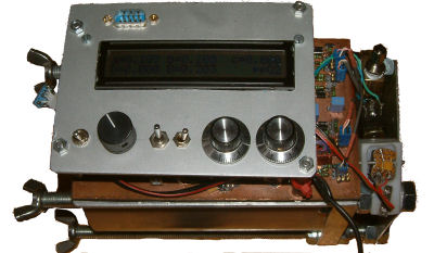
MePress - self-made pressure chamber to test O2 sensors
I was tiered of all these defective O2 sensors, never knowing when they will fail.
After several of these expensive devices and a long conversation to an old fellow in Analytical Industries I got an
adapted schema.
After some tests and some weeks I came to the conclusion that I need a test device. This was the
birth of my pressure chamber.
The aluminium housing got a bit over dimensioned, surely could afford some
hundreds of meters... why not. Feels saver when you have > 10 bar inside...
By good luck I could get an military plug converted to an pressure safe 15 pin
feed through. The rest needed was a circuit with 8 analog channels, two pressure
sensors, one inside, plus one outside for the actual barometric pressure. Three
channels measure in duplex mode 0-150 mV for the O2 sensors, and one is
needed for pressures. I also added a voltage source from 0-250 mV to be able to
test gauges. Two allow reproducible measures the chamber is pressured and
de-pressured via a valve. Two complete there is an LCD and some switches. For
best performance all values are connected by my proven ModBus interface to a
SCADA system.
|
|
|
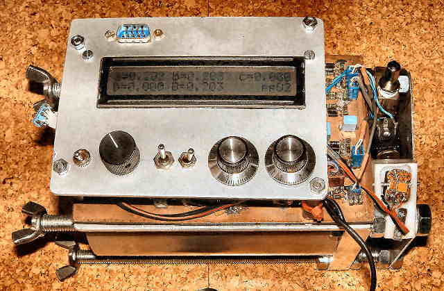
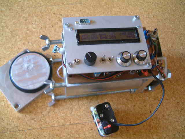
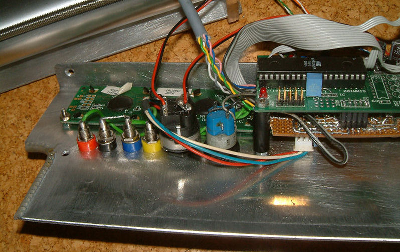
MeO2Sensortester - a new mobile version
Latest version is a lighter sensor tester, microprocessor value discussion, fully battery driven.
This allows , also on travelling, to test the electronics of your CCR.
|
Three sensors are messured in a range of 0..160mV. Combined with 12 bar maximum pressure of the chamber, pure air simulates max > 2.7 bar ppO2.
.
Additionally a low impedance output generates a 0 .. 160mv signal. This signal is intendet to test mesurement systems and can drive / simulate minimum 5 sensors.
Last not least a dc voltage input of max 20.5 volts allows to controll a battery.
|
|
|
|
Linearity of O2 sensors
Found some strange behaviour. A new senor with ca 13mV at our 960 mbar ( 450 m over
see level ) is nonlinear in low ppO2 ( till ca 0.4 bar ) than nice linear also
until 2.7 Bar ppO2. Two others, one and two years old, generate only 8 mV but
are nice linear over the full range. Seeing this I will change my habits and
make the additional effort to adjust with pure O2.
My experience with O2 sensors
In the first year I had too many defective O2 sensors, never understanding why...
By the help of an old expert in Analytical Industries www.aii1.com two reasons came into my focus.
A).
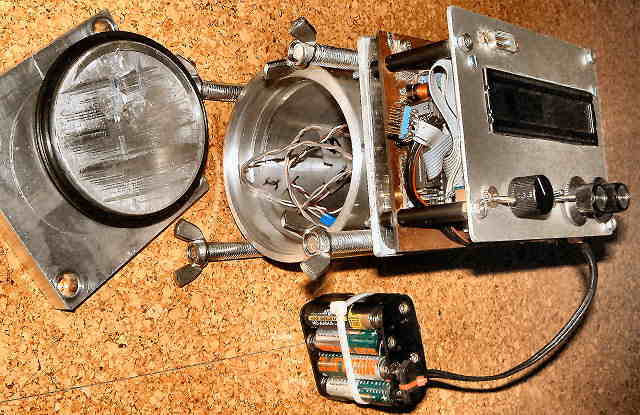
First , the sensors are sensitive to pressure differences between front and back. My closable sensor housings avoid that.
B.)
The sensors are very sensitive to reverse current. On the first thought, this could not be the reason, as I had high quality
amplifiers'. First stage to transform resistance, second OP to adapt voltage.
First stage was accurate balanced and had the defined symmetric 10k resistance.
After some discussions and head scratching I found something: Everybody sees
OP's as high resistance devices with towards zero input currents. But that is only
true after they are stabilised.... When you switch on power supply, the OP can
generate a transient current also between his two inputs.
When I came to that
point I remembered something I had observed: My sensors are always connected. When I switched my
gauges on, sometimes the values needed some time to stabilize. This makes no sense, as the sensor is something like a battery and my electronic has no
time delay parts included.
IMHO here what happens: When switching the gauge on, the first OP
clip's, and drives via feedback and input resistors current into the sensor.
Having a sensor by ca 400 ohms and the input resistors by ca 10'000 ohm (
relation 1 to 25 ) and lets assume a "unbalanced voltage of 5V only. This
reverse current is higher than the generated and will damage the sensor a bit.
The transient is only short and the sensor is going to "recover". I think the
slowly, visible "stabilizing " of the measured value could be a good hint for
such an recovering process. So what did I do ...
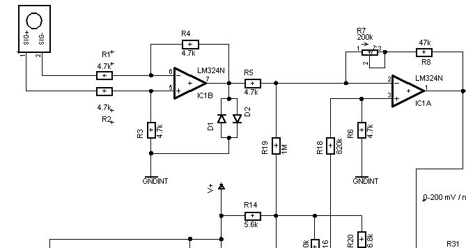
Simple just two antipapal
diodes D1 and D2 on the right place.. and since more than one year my sensors "seem" to
last longer.
I do NOT guarantee NOR take any responsability
that I found the " philosopher's stone " but at
least I have less problems since I modified my gauges.
By the help of an old expert in Analytical Industries www.aii1.com two reasons came into my focus.
A).
First , the sensors are sensitive to pressure differences between front and back. My closable sensor housings avoid that.
B.)
The sensors are very sensitive to reverse current. On the first thought, this could not be the reason, as I had high quality
amplifiers'. First stage to transform resistance, second OP to adapt voltage.
First stage was accurate balanced and had the defined symmetric 10k resistance.
After some discussions and head scratching I found something: Everybody sees
OP's as high resistance devices with towards zero input currents. But that is only
true after they are stabilised.... When you switch on power supply, the OP can
generate a transient current also between his two inputs.
When I came to that
point I remembered something I had observed: My sensors are always connected. When I switched my
gauges on, sometimes the values needed some time to stabilize. This makes no sense, as the sensor is something like a battery and my electronic has no
time delay parts included.
IMHO here what happens: When switching the gauge on, the first OP
clip's, and drives via feedback and input resistors current into the sensor.
Having a sensor by ca 400 ohms and the input resistors by ca 10'000 ohm (
relation 1 to 25 ) and lets assume a "unbalanced voltage of 5V only. This
reverse current is higher than the generated and will damage the sensor a bit.
The transient is only short and the sensor is going to "recover". I think the
slowly, visible "stabilizing " of the measured value could be a good hint for
such an recovering process. So what did I do ...
Simple just two antipapal
diodes D1 and D2 on the right place.. and since more than one year my sensors "seem" to
last longer.
I do NOT guarantee NOR take any responsability
that I found the " philosopher's stone " but at
least I have less problems since I modified my gauges.
B.) The sensors are very sensitive to reverse current. On the first thought, this could not be the reason, as I had high quality amplifiers'. First stage to transform resistance, second OP to adapt voltage. First stage was accurate balanced and had the defined symmetric 10k resistance. After some discussions and head scratching I found something: Everybody sees OP's as high resistance devices with towards zero input currents. But that is only true after they are stabilised.... When you switch on power supply, the OP can generate a transient current also between his two inputs.
When I came to that
point I remembered something I had observed: My sensors are always connected. When I switched my
gauges on, sometimes the values needed some time to stabilize. This makes no sense, as the sensor is something like a battery and my electronic has no
time delay parts included.
IMHO here what happens: When switching the gauge on, the first OP
clip's, and drives via feedback and input resistors current into the sensor.
Having a sensor by ca 400 ohms and the input resistors by ca 10'000 ohm (
relation 1 to 25 ) and lets assume a "unbalanced voltage of 5V only. This
reverse current is higher than the generated and will damage the sensor a bit.
The transient is only short and the sensor is going to "recover". I think the
slowly, visible "stabilizing " of the measured value could be a good hint for
such an recovering process. So what did I do ...
Simple just two antipapal
diodes D1 and D2 on the right place.. and since more than one year my sensors "seem" to
last longer.
I do NOT guarantee NOR take any responsability
that I found the " philosopher's stone " but at
least I have less problems since I modified my gauges.